Posts

Cooling Tower Services

When it comes to cooling tower services, we believe that having a cooling tower specialist that can cover all your cooling tower needs is the best option. That’s why we work so hard to offer a full range of cooling tower services.

We offer four basic types of cooling tower services that cover almost any cooling tower need.

Cooling tower construction: One of the key cooling tower services offered is new cooling tower construction. Inherent in this service is the design, engineering, manufacturing, construction and service for new cooling tower projects. Our new tower construction services are versatile and can meet any need because Midwest can handle design and construction of counterflow, crossflow, and ethanol cooling towers.

Repair and emergency: Repair and emergency services are essential for any time when a cooling tower is offline, for whatever reason. Down time means costly delays so access to swift emergency repair services is a must.

Reconstruction and upgrades: At the heart of the services we offer is our reconstruction and upgrade cooling tower services. Experienced engineers and design staff can create cost effective solutions for even the most challenging cooling tower design.

Maintenance and support: Prevention and maintenance are the best way to avoid the costly delays of downtown or the large scale changes brought on by reconstruction. Proper support and maintenance can increase thermal performance, reduce unplanned maintenance and emergency shutdowns, and reduce overall maintenance costs.

We also offer cooling tower thermal performance testingcooling tower inspectionscooling tower optimization and upgrades and even temporary cooling towers. These cooling tower services cover everything from new construction to support for existing towers, and everything in-between.

Contact Midwest Towers

Cooling Tower Fundamentals: The Evolution of Wooden Cooling Towers

Cooling tower construction has evolved over time as environmental concerns and new materials have become available. Although FRP is now the preferred building material, the transition from wood cooling towers to more durable materials is an interesting journey beginning with redwood construction.

The Beginning: Wooden Cooling Towers    

At the very beginning of cooling tower construction, the natural ability of redwood to inhibit decay made it the preferred material for cooling tower construction. Eventually redwood supply diminished and the building material of choice, while still wood, began to shift to Douglas Fir. While stronger, Douglas Fir decayed much faster than Redwood. To combat the decay of cooling tower lumber pressure treatment and incising were employed.

In the pressure treatment process, an aqueous solution of CCA is applied using a vacuum and pressure cycle, and the treated wood is then stacked to dry. During the process, the mixture of oxides reacts to form insoluble compounds, helping with leaching problems.

The process can apply varying amounts of preservative at varying levels of pressure to protect the wood against increasing levels of attack. Increasing protection can be applied (in increasing order of attack and treatment) for: exposure to the atmosphere, implantation within soil, or insertion into a marine environment.

Incising encourages the wood to accept chemical treatment by the process of adding small incisions along the wood.

Environmental concerns began to take their toll on wooden cooling towers as public consciousness of leaching grew. Concerns over leaching, the loss of wood preservative chemicals into the water flowing though a cooling tower, eventually led to stricter industry controls and new chemical preservative formulas. Combined with advances in steel construction, the growing cost of combating environmental concerns about wooden cooling towers caused the building material to fall out of favor.

The Ups and Downs of Steel

Type 304 stainless steel became more popular as the corrosion potential increased. Manufacturers simply substituted stainless steel for galvanized steel components. Due to cost constraints, just the cold water basin was typically up graded to SST. There were some unfortunate occasions where galvanized and stainless steels were fastened together below the water line causing rapid deterioration of the galvanized steel at the joint from galvanic action. Anyone considering mixing these materials must pay attention to the surrounding materials- particularly the fasteners. Such joints should never occur below the overflow level of the cooling tower.

Specifiers will sometimes call for type 316 SST. This is ok for nuts, bolts, and some small sub assemblies but it is largely incompatible with the tooling used by the manufacturers. It is also difficult to form. For these reasons, it is largely unavailable.

The galvanized steel cooling tower has remained the factory assembled standard. The thickness of the steel has steadily declined with more economical designs but the thickness of the zinc layer has steadily increased to a current standard of G235. (Or, 2.35oz. of zinc per sq. ft.) from a 1970’s standard of G90 (.90 oz/sq.ft.). This thickening of the sacrificial zinc layer has a very beneficial effect on cooling tower life.

Various enhancements to the galvanized steel in the form of barriers have been employed by some manufacturers. Their suitability largely depends on the local water quality.

Concrete can be an excellent construction material for basins- even side walls, fan decks, discharge stacks, and mechanical support beams. Its use beyond basins, however is not typically justified for commercial applications. Extensive concrete construction is used for architectural reasons- where the tower is disguised to look like or blend in with a building- or, the cooling tower is designed as a structure with a life expectancy equal to the facility it serves such as a hospital or university.

The New Age: FRP

FRP offers a number of advantages over traditional cooling tower construction. Fiberglass reinforced plastics advantages include:

  • Strength
  • Corrosion resistance
  • UV resistance
  • Ability to add surface treatments

new-cooling-tower-button

Contact Midwest Towers

Cooling Tower Fundamentals: Cold Weather Operations and Components

In our last cooling tower fundamentals post we covered some of the basic cooling tower components. In this cooling tower fundamentals article we will discuss the remaining basic cooling tower components and how cooling towers handle cold weather operations.

Cold Weather Operations

The most important factor is to learn to identify your own individual needs with respect to winter operation control.  There is simply no substitute for frequent visual inspections of the tower until enough operating experience has been gained to verify that a specific operating mode is effective for a given set of load and ambient conditions.

The key to successful winter start up is to preheat the water in the basin before it is directed up and over the tower.  A heat load must be applied to the tower with the hot return water bypassed directly back to the basin.  Water may then be routed up over the tower when the basin water temperature reaches approximately 80°F.  Fan speed and number of fans operating may then be used to regulate the basin water temperature.  As an added step in maintaining heat in the basin, all fans may be deactivated.

Without fans operating, air flow through the tower will continue by the thermal draft at flow rates up to one fourth that of operating the fans on low speed.  This may prove to be an alternative to cold weather operation under colder conditions.

For seasonal shutdown, heat trace the make-up line to prevent freezing and simply drain the tower.

To remove icing on support structure, should it develop, the tower may be operated without fans in operation until the hot water melts the ice and clears the supports.

It is important to note that the bypass valve must not be left open at the same time that one or both riser valves are open. 

Under severe cold weather conditions, (below zero degrees F) the normal procedure is to operate each individual fan in reverse for a period of fifteen (15) to twenty (20) minutes and to repeat this cycle once every two (2) to three (3) hours.

Air Inlet Screens

Air Inlet Screens are always part of blow thru, counterflow towers to protect people from rotating equipment . Some designs can be a hazard (or ingest trash) when accessible from the underside and require the specifier to call out additional screening. They can be a worthwhile accessory when there are nearby trees even when not required for safety reasons.

Air inlet screens should be eliminated on towers utilizing inlet ductwork. Inlet ductwork may also make it necessary to block extraneous air entry such as from the underside when towers are elevated. This is where a good sales engineer will tailor the tower to the duty.

Vibration Cutout

A vibration cutout device is used for any tower that has a fan motor to shut the motor down if excessive vibration is sensed. Small prop fans and centrifugal fans don’t normally cause enough vibration or damage to require a vibration cutout device, but they are a practical control devices for towers with large propeller fans.

Ladders and Handrails

Ladders, handrails, walkways, platforms, stairs, ect. are used where applicable depending on tower size and the specific job.

Contact Midwest Towers

Cooling Tower Fundamentals: Typical Cooling Tower Components

In our last two posts we’ve covered what makes a cooling tower work and the basic types of cooling towers. We’ve touched on some of the basic cooling tower components in our last post, but in this cooling tower fundamentals post we’d like to dig a little bit deeper into the parts that make up a cooling tower.

Fill

Most cooling towers revolve around fill, also called wet deck or surface, which is generally a PVC film type. The purpose of the fill is to maximize the contact between the air and the water, which encourages evaporation. Fill is covered in a textured patterns, usually ridges or wrinkles, so that when pieces of the fill are placed together they leave open spaces for water and air to travel. These spaces, called channels or flutes, are typically angled so that the water takes the longest possible time to travel their lengths. Individual pieces of fill are glued together to create blocks of fill which come in a variety of thicknesses and heights.

Selecting the right flute size is very important when designing a cooling tower. The smaller the flute size the higher the capacity per cubic foot, the less volume, and as a result lower costs. A marble sized flute would be more cost effective than a golf ball or baseball sized flute, and is this size is typically used in clean water application. So why use a larger sized flute? In dirty water applications, like steel mills, small flute fill would become clogged, or not work at all. A bigger, less effective fill is certainly preferable to a cooling tower that doesn’t work which is why choosing the most effective fill is vital for each cooling tower.

Bar Type Fill

Bar type fill is far less effective than film fill, but is suited to extremely dirty water applications. When bar type fill is used, water is splashed  into droplets by being plashed off of splash bars throughout the tower. Although the surface area of droplets is less than when water is spread through film fill, bar type fill allows for debris to pass through the tower and is easier to clean than film fill.

Eliminators

Eliminators are used to minimize drift. Drift is any water droplets that escape into the cooling tower discharge air. Typically they provide multidirectional changes of airflow, and a well designed eliminator will greatly reduce water loss.

Spray Tree

Spray trees can take the form of either single spray heads or, when wider coverage is needed, multiple spray heads. They are used in counterflow cooling towers to distribute water as uniformly, with minimal pressure requirements, as possible over the wet deck.

Water Basins

There are two types of water basins- hot and cold. In a crossflow tower a hot water basin takes the place of the spray tree and is used to distribute the water. A distribution or hot water basin consisting of a deep pan with holes or nozzles in its bottom is located near the top of a crossflow tower. Gravity distributes the water through the nozzles uniformly across the fill material.

Cold Water Basins collect cooled water at the bottom of the tower. They are an integral part of factory assembled designs and are built in place- typically of concrete- for field erected towers.

A Make-up Valve replaces water that exits via evaporation and bleed with fresh water. It operates somewhat like the valve found in a conventional toilet tank but is bigger and more heavy duty. Like toilet tank floats, they can function mechanically or hydraulically.

There are a lot more components that go into a cooling tower than the few we’ve discussed here, including some designed for cold weather operation. If you’re interested in learning more about cooling tower components subscribe to the Cooling Towers Blog to get the next cooling tower fundamentals article, Cold Weather and Components.

new-cooling-tower-button

Connect with Midwest Towers

Cooling Tower Fundamentals: Cooling Tower Types

All cooling towers are designed to remove waste heat from water and transfer it to the atmosphere, but there are a lot of ways to accomplish this task. Cooling towers can be categorized in a number of different ways, because there are so many differences between cooling towers.  For our purposes, we will cover three kinds of cooling towers based on how air and water flow (counterflow, crossflow, and hyperbolic)  and two types based on how the air is moved (mechanical and natural draft).

Counterflow and Crossflow

Crossflow towers utilize a type of splash fill media through which the incoming air flows horizontally across the downward flow of water from the top distribution basins. Crossflow towers tend to have lower initial and long-term costs, and are often easier to maintain. Crossflow designs are more prone to freezing, however.

cooling tower fundamentals

In counterflow towers the incoming air moves vertically upward through the fill, while the water flows downward from the distribution system. Counterflow towers tend to be more compact, but have a higher initial and operating costs because of the added power needed to force the air in opposition to the water flow.

counterflow cooling towers

Hyperbolic

Hyperbolic towers are structurally strong and use a minimum of materials, while handling large projects like nuclear or coal-fired power plants. Hyperbolic towers operate through a chimney, or stack, effect; when the air outside the cooling tower is cooler than the air inside the tower, the air outside forces the humid, inside air to travel upwards. Fill is placed around the lower portion of the tower, water is sprayed over it, and the water is cooled by the natural draft of the air moving up through the tower.


Mechanical and Natural Draft Cooling Towers

Mechanical draft towers utilize some method of mechanical force, such as a fan, to move air through the tower. Mechanical draft towers can either push air into, blow thru, or pull air out, draw thru, of the tower.

Natural draft towers utilized the buoyancy of the warm air combined with a tall chimney to naturally draw air through the tower.

Both mechanical and natural draft towers can employ either counterflow or crossflow water and air movement methods. All hyperbolic cooling towers, however, are natural draft towers.

Connect with Midwest Towers

Cooling Tower Fundamentals: Thermal Characteristics

What Makes a Cooling Tower Work?

Let’s start with the most basic example of the principles behind a cooling tower; sweat. When the human body gets too hot and needs to shed excess heat, it begins to sweat. The sweat then evaporates and creates a cooling effect over the surface of the skin, which lowers the internal body temperature. Spreading water over a surface, exposing it to the air, causes the water to evaporate and produces a drop in temperature.

Not all air is created equal, however. Have you ever been somewhere with extremely high humidity, begun to sweat, and noticed that your sweat wasn’t evaporating? If you have, it is because not all air can accept the same amount of water vapor. There is only so much moisture that air can accept, so the process of cooling through water evaporation works best in very dry air. This is why the dry heat of the Arizona desert seems more bearable than the humid heat of the Florida summer, even though the desert’s temperature is actually higher.

These ideas are what make  a cooling tower work, but there is a lot more water to cool and evaporate in a cooling tower than the small amount of water the human body generates as sweat. Which is why a cooling tower adds in a few other factors to the equation; like, fans to replace air that is already saturated with moisture, devices to constantly circulate the water over the surface, the ability to continuously add water to replace evaporated water, and a heat source to make sure the runoff is heated. While cooling towers, their maintenance, and their construction are complicated topics the basic ideas behind how they work are no sweat.

The Specifics: Or, What You Need to Know To Select a Cooling Tower

To select a cooling tower that meets your needs there are a couple of specifics that you will need:

  • Water flow rate
  • Water inlet temperature
  • Water outlet temperature
  • Wet bulb temperature

cooling-tower-fundamentals
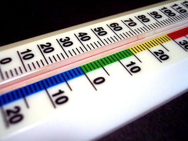
The most confusing of these specifics is the wet bulb temperature. The wet bulb temperature is used to determine the relative humidity, which changes throughout the day. The relative humidity is found by comparing the temperature of a dry thermometer with the temperature of a wet bulb thermometer. The wet bulb thermometer has water placed on its bulb, air is passed over it, the water evaporates, and the temperature is recorded. Most of the time the two thermometers will have different temperature readings, however, if the air is completely saturated with water the readings will be the same. When 100% relative humidity is reached the air can no longer accept water, the water on the bulb cannot evaporate, and the temperature will be the same as the dry bulb. So, the lower the wet bulb reading, the lower the humidity, the more moisture the air can accept,  the more heat a cooling tower can be expected to reject.

Many wet bulb readings are taken and recorded to determine the maximum wet bulb reading; the size of the cooling tower is determined by the max wet bulb reading. When sizing a cooling tower you want to err on the side of caution and size for the highest wet bulb reading because, your tower will then be  oversized and the leaving water temperature will simply be lower.

How Fast Does a Cooling Tower Transfer Heat?

A cooling tower doesn’t actually control the rate of heat transfer; a cooling tower only transfers the heat it has been given. Heat transfer and evaporation rates do not vary, regardless of the size of the cooling tower. Wet bulb temperature, along with cooling tower size and flow rate, determine inlet and outlet water temperatures. However, the difference between inlet and outlet temperature is not determined by the cooling tower. For example, you could cool water from 90 to 80, or 100 to 90, but  the 10 degree difference is not affected by the size of the tower. So, while you can’t change the rate of heat transfer, you can increase performance by increasing the surface area or booting the cfm.

Subscribe to the Cooling Towers Blog to get the next cooling tower fundamentals article, Cooling Tower Types.

Connect with Midwest Towers

Midwest Cooling Towers Rebuilds a Tired Power Plant Cooling Tower

Challenge

Rebuild and refurbish a tired and unsafe 44-year old two-cell wood cooling tower located at a midwestern municipal power plant.

Solution

Midwest Cooling Towers was contacted to inspect the cooling tower and found it in bad shape. In the ensuing six years, an explosion at a nearby industrial plant further damaged the cooling tower.

Time came to undertake the repair/rebuild project. The originally planned replacement of approximately 50% of the structure turned into much more when the project started. It was determined that the structure was in much worse shape and for safety’s sake the cooling tower was almost entirely replaced.

Midwest Cooling Towers was able to reuse the mechanical equipment system (gear boxes, driveshafts, motors, fans, supports) and one fan stack. All the rest of the cooling tower was replaced: new structure, fill, eliminators, distribution system, fan deck, casing, and two fan stacks.

The result was a new life for a tired cooling tower. And, a very pleased customer

Connect with Midwest Towers

Midwest Cooling Towers Rapidly Completes Cooling Tower Reconstruction

Challenge

Demolish an existing approximately 35-year old 10-cell wood cooling tower located at a Midwestern power plant and erect a new 10-cell fiberglass cooling tower on the existing concrete basin within a tight six-week outage window.

Solution

Midwest Cooling Towers took on the challenge. We managed five subcontractors, logistically working side-by-side with each other and our own crew in tackling this project.

Midwest provided engineering, design, drafting, manufacturing, material, field supervision, project management and labor. The Midwest crew consisted of three field superintendents and 70 to 80 daily laborers.

Midwest’s subsidiary company, Beetle Plastics, was also involved in the project, providing the large 20” fiberglass pipe used for the ten risers and the internal water distribution crossovers. Beetle Plastics also supplied the three 24” diameter bypass pipes, expansion joints for the risers and other various components.

Midwest was chosen for the job because of our expertise in the new concept of fiberglass crossflow cooling towers.

The contract required a minimum of eight cells operational at the end of the scheduled six-week outage.

Because of the aggressive schedule, successful completion of this project required extensive planning.

The cooling tower structure, or bent lines, and the fill grids were pre-assembled on site prior to the outage. The fan stacks, mechanical support sub-assemblies and stairways were also pre-assembled on site.

When the outage started we were able to move quickly. Demolition of the existing cooling tower took just three days.

The assembly of the fiberglass bent lines was very efficient. Eighty-one bent lines were stood in five days.

Unlike a wood tower, the columns can be one piece instead of two or three pieces. This reduces the amount of time and material it takes to put a bent line together.

The extensive planning, hard work and smart project management garnered positive results. Midwest not only met the aggressive schedule, we exceeded expectations by handing over all 10 cells to the customer four days ahead of schedule.

Most importantly, the entire project was completed with no reportable safety incidents.

In addition, Midwest Cooling Towers was recognized with a performance bonus.

Connect with Midwest Towers

Efficient Cooling Tower Demolition and Crossflow Tower Construction

Challenge

Demolish two existing wood six-cell cooling towers and complete eight of 12 cells in two new fiberglass cooling towers within a tight six-week outage window.

Solution

Midwest teamed up with Precision Cooling Towers, a contractor out of Henderson, Kentucky to tackle this project.

Midwest provided engineering, design, drafting, manufacturing, material, and field assistance. Precision provided the labor to build the towers.

Although Precision was providing the labor, Midwest provided a field advisor/consultant to provide expertise in the construction of our fiberglass towers.

Midwest was chosen for the job because of our expertise in the new concept of fiberglass crossflow cooling towers.

The plant had a scheduled outage for six weeks. Four of the six cells on each tower (8 of 12 total) had to be operational at the end of the six-week outage.

Although the schedule for the six-week outage was very aggressive, the deadline was met. The entire external structure and eight of 12 cells were completed on time.

Successful completion of this project was possible due to extensive planning.

The bent lines were assembled on site prior to the outage. This allowed us to complete the demolition and erect both structures 10 days after the outage started. 110 bent lines were stood in seven days (55 per tower).

The assembly of the fiberglass bent lines was very efficient. Unlike a wood tower, the columns can be one piece instead of two or three pieces. This reduces the amount of time and material it takes to put a bent line together

The utility customer was very pleased with the finished project.

Connect with Midwest Towers